
![]()
Task 1 Introduction
 Malware often works by abusing the way systems are designed. Therefore, to understand how malware works, it is essential that we know the architecture of the systems they are running in. In this room, we will get a brief overview of the x86 architecture from a malware analysis point of view. Please note that there might be a lot of details of the x86 architecture that we will be skipping over, but that is because they are not related to malware analysis.
Learning Objectives:
Summing up, we will be covering the following topics in this room.
- Overview of CPU architecture and its components
- Different types of CPU registers and their usage
- Memory layout as viewed by a program
- Stack layout and stack registers
So let’s dive into the room and learn about the above-mentioned topics.
Answer the questions below
Go through the Learning Objectives
Completed
Task 2 CPU architecture overview
The CPU architecture that is most widely used is derived from the Von Neumann architecture. A brief overview of this architecture is demonstrated in the below diagram.

This diagram shows that the CPU has three components: the Arithmetic Logic Unit (ALU), the Control Unit, and the Registers. The CPU interacts with memory and I/O devices outside the CPU. Let’s learn about each of the components mentioned in the diagram below.
Control Unit:
The Control Unit gets instructions from the main memory, depicted here outside the CPU. The address to the next instruction to execute is stored in a register called the Instruction Pointer or IP. In 32-bit systems, this register is called EIP, and in 64-bit systems, it is called RIP.
Arithmetic Logic Unit:
The arithmetic logic unit executes the instruction fetched from the Memory. The results of the executed instruction are then stored in either the Registers or the Memory.
Registers:
The Registers are the CPU’s storage. Registers are generally much smaller than the Main Memory, which is outside the CPU, and help save time in executing instructions by placing important data in direct access to the CPU.
Memory:
The Memory, also called Main Memory or Random Access Memory (RAM), contains all the code and data for a program to run. When a user executes a program, its code and data are loaded into the Memory, from where the CPU accesses it one instruction at a time.
I/O devices:
I/O devices or Input/Output devices are all other devices that interact with a computer. These devices include Keyboards, Mice, Displays, Printers, Mass storage devices like Hard Disks and USBs, etc.
In short, when a program has to be executed, it is loaded into the memory. From there, the Control Unit fetches one instruction at a time using the Instruction Pointer Register, and the Arithmetic Logic Unit executes it. The results are stored in either the Registers or the Memory.
Answer the questions below
In which part of the Von Neumann architecture are the code and data required for a program to run stored?
Memory
What part of the CPU stores small amounts of data?
Registers
In which unit are arithmetic operations performed?
Arithmetic Logic Unit
Task 3 Registers overview
Registers are the CPU’s storage medium. The CPU can access data from the registers quicker than any other storage medium; however, its limited size means it has to be used effectively. For this purpose, the registers are divided into the following different types:
- Instruction Pointer
- General Purpose Registers
- Status Flag Registers
- Segment Registers
Let’s go through each of these registers one by one below:
The Instruction Pointer:
The Instruction Pointer is a register that contains the address of the next instruction to be executed by the CPU. It is also called the Program Counter. It was originally a 16-bit register in the Intel 8086 processor (from where the term x86 originated) and was abbreviated as IP. In 32-bit processors, the Instruction Pointer became a 32-bit register called the EIP or the Extended Instruction Pointer. In 64-bit systems, this register became a 64-bit register called RIP (the R here stands for register).
General-Purpose Registers
The General-Purpose registers in an x86 system are all 32-bit registers. As the name suggests, these are used during the general execution of instructions by the CPU. In 64-bit systems, these registers are extended as 64-bit registers. They contain the following registers.
EAX or RAX:
This is the Accumulator Register. Results of arithmetic operations are often stored in this register. In 32-bit systems, a 32-bit EAX register is present, while a 64-bit RAX register is present in 64-bit systems. The last 16 bits of this register can be accessed by addressing AX. Similarly, it can also be addressed in 8 bits by using AL for the lower 8 bits and AH for the higher 8 bits.
EBX or RBX:
This register is also called the Base Register, which is often used to store the Base address for referencing an offset. Similar to the EAX/RAX, it can be addressed as 64-bit RBX, 32-bit EBX, 16-bit BX, and 8-bit BH and BL registers.
ECX or RCX:
This register is also called the Counter Register and is often used in counting operations such as loops, etc. Similar to the above two registers, it can be addressed as 64-bit RCX, 32-bit ECX, 16-bit CX, and 8-bit CH and CL registers.
EDX or RDX:
This register is also called the Data Register. It is often used in multiplication/division operations. Similar to the above registers, it can be addressed as 64-bit RDX, 32-bit EDX, 16-bit DX, and 8-bit DH and DL registers.
ESP or RSP:
This register is called the Stack Pointer. It points to the top of the stack and is used in conjunction with the Stack Segment register. It is a 32-bit register called ESP in 32-bit systems and a 64-bit register called RSP in 64-bit systems. It can not be addressed as smaller registers.
EBP or RBP:
This register is called the Base Pointer. It is used to access parameters passed by the stack. It is also used in conjunction with the Stack Segment register. It is a 32-bit register called EBP in 32-bit systems and a 64-bit register called RBP in 64-bit systems.
ESI or RSI:
This register is called the Source Index register. It is used for string operations. It is used with the Data Segment (DS) register as an offset. It is a 32-bit register called ESI in 32-bit systems and a 64-bit register called RSI in 64-bit systems.
EDI or RDI:
This register is called the Destination Index register. It is also used for string operations. It is used with the Extra Segment (ES) register as an offset. It is a 32-bit register called EDI in 32-bit systems and a 64-bit register called RDI in 64-bit systems.
R8-R15:
These 64-bit general-purpose registers are not present in 32-bit systems. They were introduced in the 64-bit systems. They are also addressable in 32-bit, 16-bit, and 8-bit modes. For example, for the R8 register, we can use R8D for lower 32-bit addressing, R8W for lower 16-bit addressing, and R8B for lower 8-bit addressing. Here, the suffix D stands for Double-word, W stands for Word, and B stands for Byte.
Answer the questions below
Which register holds the address to the next instruction that is to be executed?
Instruction Pointer
Which register in a 32-bit system is also called the Counter Register?
32-bit registers have a prefix of ‘E’ before their 16-bit names.
ECX
Which registers from the ones discussed above are not present in a 32-bit system?
These registers were introduced in 64-bit systems.
R8-R15
Task 4 Registers - Continued
Status Flag Registers:
When performing execution, some indication about the status of the execution is sometimes required. This is where the Status Flags come in. This is a single 32-bit register for 32-bit systems called EFLAGS, which is extended to 64-bits for 64-bit systems, and called RFLAGS in the 64-bit system. The status flags register consists of individual single-bit flags that can be either 1 or 0. Some of the necessary flags are discussed below:
Zero Flag:
Denoted by ZF, the Zero Flag indicates when the result of the last executed instruction was zero. For example, if an instruction is executed that subtracts a RAX from itself, the result will be 0. In this situation, the ZF will be set to 1.
Carry Flag:
Denoted by CF, the Carry Flag indicates when the last executed instruction resulted in a number too big or too small for the destination. For example, if we add 0xFFFFFFFF and 0x00000001 and store the result in a 64-bit register, the result will be too big for the register. In this case, CF will be set to 1.
Sign Flag:
The Sign Flag or SF indicates if the result of an operation is negative or the most significant bit is set to 1. If these conditions are met, the SF is set to 1; otherwise, it is set to 0.
Trap Flag:
The Trap Flag or TF indicates if the processor is in debugging mode. When the TF is set, the CPU will execute one instruction at a time for debugging purposes. This can be used by malware to identify if they are being run in a debugger.
| General Registers | Segment Registers | Status Registers | Instruction Pointer |
| RAX, EAX, AX, AH, AL | CS | EFLAGS | EIP, RIP |
| RBX, EBX, BX, BH, BL | SS | ||
| RCX, ECX, CX, CH, CL | DS | ||
| RDX, EDX, DX, DH, DL | ES | ||
| RBP, EBP, BP | FS | ||
| RSP, ESP, SP | GS | ||
| RSI, ESI, SI | |||
| RDI, EDI, DI | |||
| R8-R15 |
Segment Registers:
Segment Registers are 16-bit registers that convert the flat memory space into different segments for easier addressing. There are six segment registers, as explained below:
Code Segment: The Code Segment (CS ) register points to the Code section in the memory.
Data Segment: The Data Segment (DS) register points to the program’s data section in the memory.
Stack Segment: The Stack Segment (SS) register points to the program’s Stack in the memory.
Extra Segments (ES, FS, and GS): These extra segment registers point to different data sections. These and the DS register divide the program’s memory into four distinct data sections.
Answer the questions below
Which flag is used by the program to identify if it is being run in a debugger?
Trap Flag
Which flag will be set when the most significant bit in an operation is set to 1?
Sign Flag
Which Segment register contains the pointer to the code section in memory?
Code Segment
Task 5 Memory overview
When a program is loaded into the Memory in the Windows Operating System, it sees an abstracted view of the Memory. This means that the program doesn’t have access to the full Memory; instead, it only has access to its Memory. For that program, that is all the Memory it needs. For the sake of brevity, we will not go into the details of how the Operating System performs abstraction. We will look at the Memory as a program sees it, as that is more relevant to us when reverse-engineering malware.
The diagram here is an overview of the typical memory layout for a program. As can be seen, Memory is divided into different sections, namely Stack, Heap, Code, and Data. While we have shown the four sections in a particular order, this can be different from how they will be all the time, e.g., the Code section can be below the Data section.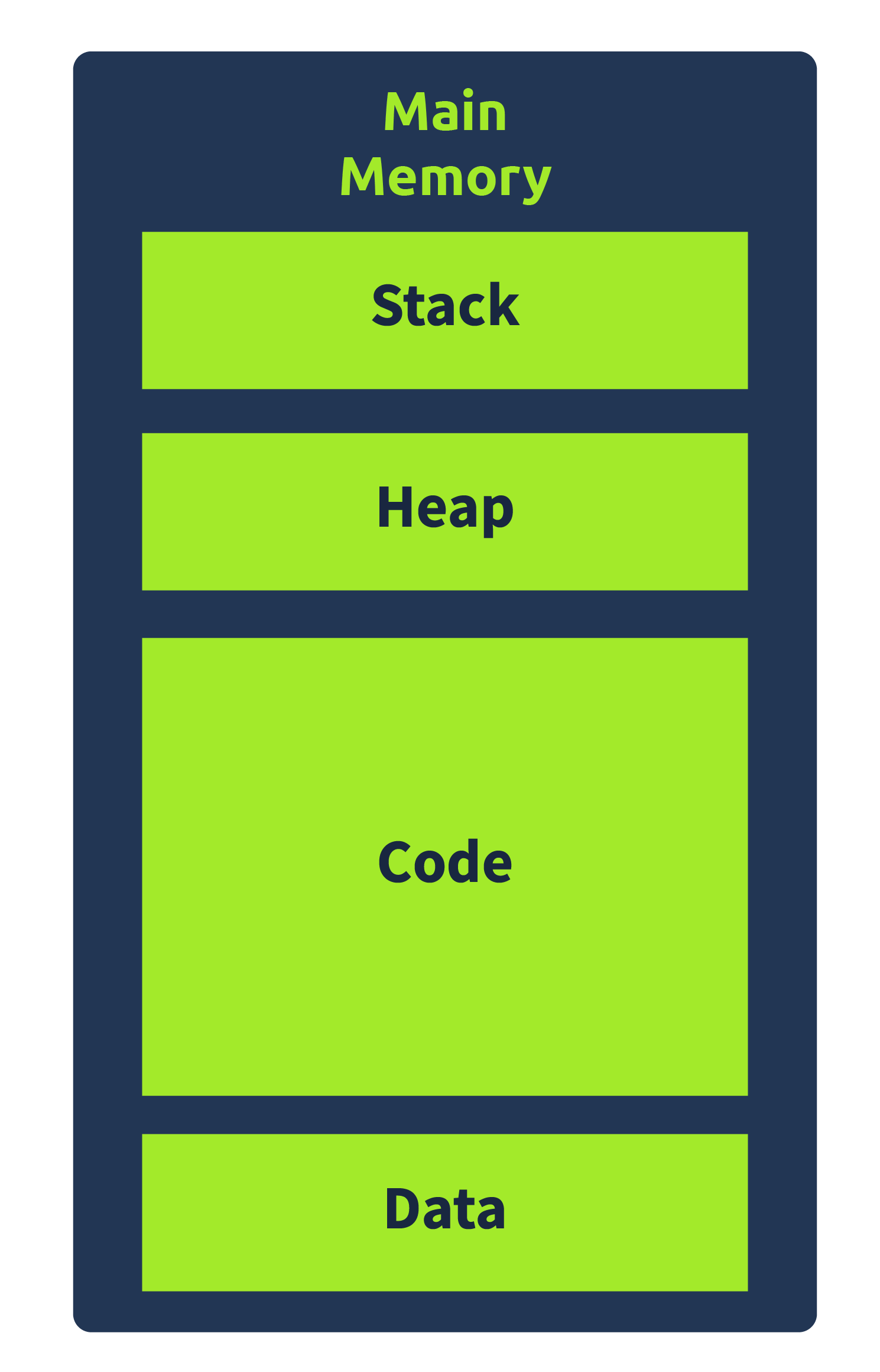
We can find a brief overview of the four sections below.
Code:
The Code Section, as the name implies, contains the program’s code. Specifically, this section refers to the text section in a Portable Executable file, which includes instructions executed by the CPU. This section of the Memory has execute permissions, meaning that the CPU can execute the data in this section of the program memory.
Data:
The Data section contains initialized data that is not variable and remains constant. It refers to the data section in a Portable Executable file. It often contains Global variables and other data that are not supposed to change during the program’s execution.
Heap:
The heap, also known as dynamic Memory, contains variables and data created and destroyed during program execution. When a variable is created, memory is allocated for that variable at runtime. And when that variable is deleted, the memory is freed. Hence the name dynamic memory.
Stack:
The Stack is one of the important parts of the Memory from a malware analysis point of view. This section of the Memory contains local variables, arguments passed on to the program, and the return address of the parent process that called the program. Since the return address is related to the control flow of the CPU’s instructions, the stack is often targeted by malware to hijack the control flow. You can look at the Buffer Overflows room to learn how this happens. We will cover more details about the stack in the next task.
Answer the questions below
When a program is loaded into Memory, does it have a full view of the system memory? Y or N?
N
Which section of the Memory contains the code?
Code
Which Memory section contains information related to the program’s control flow?
Stack
Task 6 Stack Layout
View Site
The Stack is a part of a program’s memory that contains the arguments passed to the program, the local variables, and the program’s control flow. This makes the stack very important regarding malware analysis and reverse engineering. Malware often exploits the stack to hijack the control flow of the program. Therefore it is important to understand the stack, its layout, and its working.
The stack is a Last In First Out (LIFO) memory. This means that the last element pushed onto the stack is the first one to be popped out. For example, if we push A, B, and C onto the stack, when we pop out these elements, the first to pop out will be C, B, and then A. The CPU uses two registers to keep track of the stack. One is the Stack Pointer (the ESP or RSP), and the other is the Base Pointer (the EBP or RBP).
The Stack Pointer:
The Stack Pointer points to the top of the stack. When any new element is pushed on the stack, the location of the Stack Pointer changes to consider the new element that was pushed on the stack. Similarly, when an element is popped off the stack, the stack pointer adjusts itself to reflect that change.
The Base Pointer:
The Base Pointer for any program remains constant. This is the reference address where the current program stack tracks its local variables and arguments.
Old Base Pointer and Return Address:
Below the Base Pointer lies the old Base Pointer of the calling program (the program that calls the current program). And below the old Base Pointer lies the Return Address, where the Instruction Pointer will return once the current program’s execution ends. A common technique to hijack control flow is to overflow a local variable on the stack such that it overwrites the Return Address with an address of the malware author’s choice. This technique is called a Stack Buffer Overflow.
Arguments:
The Arguments being passed to a function are pushed to the stack before the function starts execution. These arguments are present right below the Return Address on the stack.
Function Prologue and Epilogue:
When a function is called, the stack is prepared for the function to execute. This means that the arguments are pushed to the stack before the start of the function execution. After that, the Return Address and the Old Base Pointer are pushed onto the stack. Once these elements are pushed, the Base Pointer address is changed to the top of the stack (which will be the Stack Pointer of the caller function at that time). As the function executes, the Stack Pointer moves as per the requirements of the function. This portion of code that pushes the arguments, the Return Address, and the Base Pointer onto the Stack and rearranges the Stack and Base Pointers is called the Function Prologue.
Similarly, the Old Base Pointer is popped off the stack and onto the Base Pointer when the function exits. The Return address is popped off to the Instruction Pointer, and the Stack Pointer is rearranged to point to the top of the stack. The part of the code that performs this action is called the Function Epilogue.
Click the View Site button at the top of the task to launch the static site in split view. Now, hop on the attached static site and find the flag by arranging the stack correctly.
Answer the questions below
Drag and drop the stack pieces on the left into the correct stack position on the right.

THM{SMASHED_THE_STACK}

 Follow the instructions in the attached static site and find the flag. What is the flag?
THM{SMASHED_THE_STACK}
Task 7 Conclusion
That concludes this room on the primer of x86-64 system architecture. In this room, we learned:
- The Von Neumann CPU architecture
- Different components of a CPU
- Different types of CPU registers
- Memory and its different sections
- Stack layout of a program in memory
Let us know what you think about this room on our Discord channel or Twitter account. See you around.
Answer the questions below
Join the discussion on our social channels
Completed